2001 Astra 1.6 - Misfire
This next problem comes from a 2001 Vauxhall Astra 1.6 with a misfire problem under load. The repair shop had diagnosed the coil pack as faulty and fitted a new unit with plugs, but this made no difference to the problem. Before they went any further I was called in for a second opinion. Not least, the tech involved wanted to know how his checks that he’d relied on for countless previous ignition problems had somehow let him down with this one.
Let’s start from the beginning. When I arrived at the car, the new coil pack was still fitted and the engine MIL was flagged. Checking for DTCs revealed the dreaded P0300 GENERAL MISFIRE logged – absolutely no use whatsoever. Retrieving the freeze-frame data only pointed to the same DTC with the engine at moderate load and throttle part open, again not a lot to build on, but as this misfire was present and consistent there was no need to start chasing a particular operating or faulting condition.
I start with ignition as it’s often the most accessible. If direct HT access is awkward then monitoring mutual induction through the coil primary can yield big results. This vehicle’s ignition system has four individual COPs lined up in one sealed unit and placed over the plugs, and the coil drivers are external to the coil pack and built into the ECM, making the coil primary available for analysis.
A quick test was to current-clamp the shared ignition live feed to all four COPs. The purpose behind this is to note and compare the amps consumed by each coil primary: if a good current trace is displayed then we have established the circuit supply voltage, ground path and circuit resistance. Needless to say, each captured trace should be very similar, having a good self-inductive ramp, a good peak current, and a clean release.
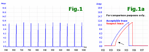
Shared Ignition Current Waveform
Included in any coil resistance is not only physical ohms of the wire wound inside the coil, but also a brief period of self-inductance which opposes current flow and acts as a resistance. Hence we see the current gradually building up rather than flowing at full strength instantaneously.
At a glance they all appeared normal, yet when examined closer I found every 4th current ramp displaying different characteristics. Fig.1a shows a good trace overlaid on our suspect trace. The sudden hike at the start of the inductive ramp suggests a winding short inside the coil, so further monitoring of the HT burn-time is needed. This investigation was taking an unexpected turn towards a coil failure, but this was the new coil pack I was testing. Were there two failed coil packs on the same vehicle?

Waveforms - Snap Throttle Test
* ChA (blue trace) is measuring ignition power supply shared amongst coils
* ChB (red trace) is hooked up to CYL3 coil primary command
* ChC (green trace) is hooked up to CYL1 coil primary command
* ChD (orange trace) is hooked up to CYL2 coil primary command
* (CYL 4 has been sacrificed for the benefit of including the current trace)
Fig.2 was captured during a typical snap throttle test. Engine speed is calculated to be about 2400 rpm and was ascending during the WOT state. The problem cylinder is identified as No.3, with no burn-time, indicating that no spark exists at all. Perhaps not surprisingly, neither are there any coil oscillations. Although the primary inductive kick was found at about 250 V and at a level comparable with the remaining firing cylinders, it is a poor indication of the secondary voltage available.
Monitoring secondary information through the primary is only useful for burn-time analysis. This problem is simply a weak coil and confirms what the current probe picked up earlier; in fact, this coil pack is displaying various ignition issues. Looking at the firing cylinders, I picked out the best burn time at 0.57 ms for CYL 1, but expect double that for a healthy coil: at least 1 ms. And even on these firing cylinders there are no coil oscillations present when the burn-time finishes, so secondary energy is used up very quickly.
Premature coil failure (and you cannot get more premature than a brand-new coil failing) is likely due to external influences. For example, having the coil firing open-ended puts it under tremendous stress and pushes insulation beyond normal limits. However, I don’t think such an extreme is the case here, but I think this unit was ready to cause problems from the moment the box was opened. I recommended another new coil pack and was asked to stick around by a very cautious and slightly sceptical garage owner.
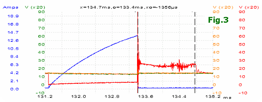
New Coil Pack - Waveforms
With the new coil pack in place, Fig.3 was a typical capture taken at snap throttle and just off idle speed. What a difference! The key points of interest include the extinguished hike at the beginning of the current ramp; the peak current that has increased to 14 amps, a full 2 amps up on the previous coil; most importantly a burn time that’s present and holding for a good 1.3 ms; and finally the presence of coil oscillations before and after the burn time. The other three coils all showed similar improvements.
If you buy a new part or component, it’s not unreasonable to automatically expect it to work. If electrical troubleshooting isn’t challenging enough then a faulty new component could send you on a costly ghost hunt. I can only guess that the dud coil pack came from a Friday afternoon batch.
In response to the tech’s question about why his own checks had let him down, I replied “They haven’t”.
courtesy of Nick Hibberd - Pico Tech
www.autoequipment.com.au |